Rectifiers
Basic CP Inspection Information
As client representatives and inspectors with over 100 years combined experience, we have run across a host of misconceptions and common problems associated with Cathodic Protection (CP) inspections. Common misconceptions regarding pipeline inspection techniques are discussed elsewhere on this website (here). Beyond inspection methods however, there are a number of bedrock principles that merit discussion in their own right. The following is information that we have gathered over our years of performing CP inspections
Training and Experience Matter
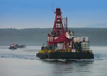
All testing methodologies require properly trained personnel using the right calibrated equipment and adherence to procedures that ensure accurate data collection. To ensure success, it is essential that a competent marine cathodic protection survey contractor manage the front-end planning and project interface of their equipment to support services including navigation, ROV, and vessels. It is important to note that the pipeline operator’s underwater contractor and/or in-house underwater Subject Matter Experts (SME) are likely former divers or ROV technicians, rather than CP survey personnel. The SME may not have the expertise to ensure that the correct marine spread is contracted, that the various interface issues are resolved successfully, or to provide QA during the survey.
“Good” CP Readings Aren’t Always a Good Thing
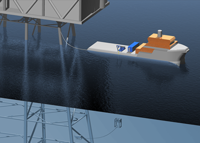
During a CP inspection, the crew expects that a range from -700mV to -1300mV will be observed for a pipeline or structure’s potentials and anything more negative than -800 mV is “good.” What is often overlooked is that a CP inspection system can be influenced by a number of factors including: trailing wire or deck lead positioning on the vessel (induced voltage); the vessel’s or ROV’s CP system (improper system isolation); or, with ROV surveys, a faulty grounding system or induced voltage in the ROV system anywhere between the ROV and control console. Without training in understanding and identifying these anomalous “cathodic potential” values and how to take corrective action, the wrong data may be collected. We have reviewed a number of reports for structures and pipelines that are protected only with aluminum alloy or zinc anodes with reported potentials more negative than -1200mV. Even though it is not possible for these structures to be more negative than -1100mV, no questions were raised because the pipeline or structure was “protected”. In most instances, erroneous data can be a larger problem than no data in that with no data, you know what you don’t know. With erroneous data, you don’t really know what you think you know..
Risers Don’t Tell the Whole Story
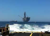
As a standalone, riser potentials provide zero indication of a pipeline’s potential 1500-ft from the riser, regardless of whether the riser is shorted to or isolated from the structure.
“Stab Potentials” are Good, Except…
Bare steel stab potentials are the most accurate potentials obtainable for a location, provided they are not adjacent to an anode. Unfortunately, anode stab potentials (as a standalone) are not representative of the pipeline’s potential. An anode stab provides the most negative (best) potential obtainable at and around a particular location, meaning the anode stab identifies the most negative potential possible on the pipeline in the anode’s vicinity. The pipeline’s potential distant from the anode cannot be better, but it certainly may be worse…
Impressed Current Systems
When performing CP surveys on structures protected with an impressed current system, we recommend and can install synchronized current interrupters on all rectifiers affecting the facility. We have witnessed potential changes (IR drop) in excess of 500mV between rectifier “on” and “off” values.